Every optical connector has a ferrule — the precision engineered part that holds the fibre in place and aligns it with its mate. On paper, they look the same, and it can be tempting to think of them as a commodity. But like most things in optical fibre, quality matters. A few microns of concentricity error, hole diameter drift, or ovality can shift the fibre core enough to cause measurable insertion loss.
The lower your loss budget, the more critical the connector quality is. In modern networks the limit is already very low. 10GBase-SR requires a maximum channel loss of 2.9dB, while 40GBase-SR4’s maximum is 1.5dB. When you add fibre loss over your length, there is no room for questionable quality.
In a perfect world, the cores align perfectly every time. But the reality is always a compromise. The ferrule is a simple yet wonderfully complex piece of engineering, with a number of things that impact performance. The ferrule bore diameter is the first of those. Too tight and it becomes difficult to insert the fibre during manufacture and impacts performance under temperature cycling. Too loose and the fibre has room to shift around in the empty space. The concentricity of the bore relative to the ferrule outer diameter is also critical. If the offset is too great, the fibre alignment will be compromised. These underscore the importance of selecting the right ferrule as a base platform for the performance you need.
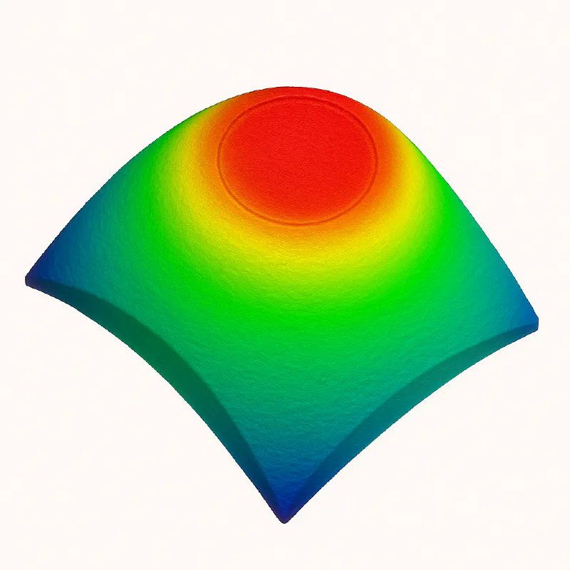
Beyond the ferrule, the polishing process has a massive impact. The method of polish impacts the finished geometry. The radius of curvature, apex offset, protrusion or undercut, and surface roughness all impact the alignment with the mated connector, and ultimately loss.
Even high-quality ferrules have variations. The question is how those variations show up in testing — and in your actual network.
Reference–Random vs. Random–Random Mating
Insertion loss isn’t a fixed property of a connector. It’s a property of a connector mated to another connector.
Reference–Random One connector is a highly precise reference-grade connector. It’s manufactured to tighter tolerances than typical field connectors. You mate each connector under test to this known-good reference. The result is lower and more consistent loss values, because the reference ferrule compensates for much of the variability.
Random–Random You mate two connectors from the general production population. This is closer to what happens in the field, two real connectors with their own tolerances lining up (or not). Variability goes up, and average loss is usually worse than Reference–Random tests.
Why the Difference Matters
A connector that looks great in manufacturing might disappoint in a real rack, because in the wild you rarely mate to a perfect reference ferrule. That’s why some manufacturers quietly prefer to publish reference-random: they look better on datasheets.
In a deployment, especially in patching environments where connectors are re-mated hundreds of times, Random–Random results are a better predictor of reality. You’re only as good as your worst matching pair.
Tolerance Stack-Up in the Field
The insertion loss in a Random-Random scenario is a mix of a few things:
- Ferrule concentricity error from both connectors.
- Fibre core/cladding diameter variation.
- Polish geometry conformance.
- Dirt or contamination.
Even if each individual connector meets the specification, the combination can push a pair over the limit, especially in multi-connector channels where loss adds up fast. If you budget on the published loss specification, you can find it difficult or impossible to acheive that performance in the field.
IEC 61753-1 As a Guide Post
Helpfully, the IEC has a published standard that helps define what “good” looks like for passive fibre optic components: IEC 61753-1. Under IEC 61753-1, random mated connector pairs are classified A, B, C, or D based on their measured insertion loss and return loss.
- Grade A is the tightest tolerance — the lowest average insertion loss and the most consistent performance between random pairs.
- Grade B is still high-quality, but with slightly looser limits.
- Grade C and D allow progressively higher loss and are often used where budget matters more than squeezing every dB of margin.
| IEC Random-Mating Grade | Mean IL ≤ (dB) | Max IL ≤ (dB) for ≥ 97 % of Samples | Notes |
|---|---|---|---|
| A | 0.07 dB | 0.15 dB | Grade A not yet finalised; adopted in practice |
| B | 0.12 dB | 0.25 dB | Readily available |
| C | 0.25 dB | 0.50 dB | Very common; often not published |
| D | 0.5 dB | 1.00 dB | Poorer performance; often not published |
For a buyer, these grades are a shortcut to knowing what you’re getting. The key is that IEC 61753-1 makes the grading comparable across vendors. A Grade B connector from one supplier must meet the same test conditions and limits as a Grade B from another. That means you can line up two quotes, check the grade, and know you’re not comparing apples to oranges.
What to Do About It
- Check the spec sheet carefully — Does it specify an IEC grade? If it’s silent, assume the loss limit provided is Reference-Random, and you can expect higher loss in the field.
- Buy from a supplier who controls ferrule sourcing tightly — Not all “Zirconia ferrules” are created equal - cheaper vendors use worse ferrules.
- Clean before every mate — Dirt amplifies tolerance misalignment effects. (Insert shameless plug for our ClickPRO connector cleaners)
- Design for margin — If your link budget is tight, don’t rely on best-case insertion loss numbers.


